Air Taxi Prototype Crash at Cotswold Airport
On the 9th of August 2023, a VX4 crashed at Cotswold Airport in Gloucestershire during a test flight over the runway.
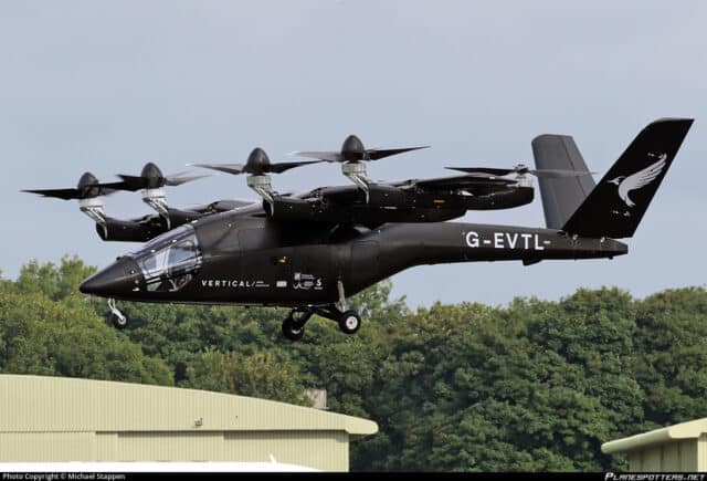
The VX4 is a prototype air taxi, designed and manufactured by Vertical Aerospace Ltd based in Bristol in the west of England. There’s some confusion (at least, I’m confused) about the naming conventions. The aircraft registered as G-EVTL is referred to in the accident report as a VA-1X (not to be confused with their very first prototype, a quadcopter called VA-X1). In company documentation from 2020, the prototype aircraft is initially referred to as a VA-X4. In the media and the current website, it’s called the VX4. In any event, G-EVTL is the fullscale prototype of an electric high-wing aircraft with eight propellers which is capable of vertical take-off and landings (eVTOL). The five-seater aircraft (pilot and four passengers) is pitched as an urban air taxi, with plenty of room for luggage. Vertical Aerospace say that it is 30 times quieter than the equivalent helicopter with zero operating emissions. The prototype completed its first tethered flight in 2022 and aims to be the first certified winged all-electric Vertical Take-Off and Landing aircraft. They already have orders for up to 1,000 aircraft, with customers including American Airlines, Virgin Atlantic and AirAsia.
The prototype is designed as a piloted aircraft but the initial test flight in July 2023 was unmanned. The prototype lifted off, hovered and flew at a speed of 40 knots before landing. Aviation photographer Michael Stappen was at Cotswold Airport and got a photograph of that first flight.
The goal is to offer safe and energy-efficient city transport with cruise speeds of 150 mph and a range of up to 100 miles. Vertical Aerospace stated at the time that this marked their next phase of testing: crewed flight missions. Luckily, the next flight was also unmanned.
The flight on the 9th of August was a test of the aircraft’s performance in the case of an engine failure during hover. G-EVTL has eight electric propulsion units (EPUs) powered by lithium-ion battery subpacks. Each EPU consists of a three-phase motor, an inverter and a thermal management system and drives one propeller. The eight carbon-composite propellers are placed on the wings: four on the leading edge and four on the trailing edge. The forward five-bladed propellers tilt in an angle range of 0° (straight ahead) to 100° (slightly past vertically upwards), allowing the aircraft to shift between vertical lift and forward propulsion. The rear four-bladed propellers are fixed into place to point vertically upwards.
For the unmanned test, the pilot controlled the aircraft from a remote cockpit with a curved screen offering a panoramic view of the instruments. A second pilot maintained visual contact with the aircraft. Additional team members monitored the aircraft status and were able to quickly speak to the pilot as needed.
G-EVTL lifted off with all EPUs operating. The front tilting propellers are numbered 1 – 4 from left to right. Once stable in ground effect, the pilot shut down EPU1 (left-side outboard) to simulate the performance in the case of an engine failure. Then the pilot carefully climbed to 30 feet above the runway.
The system response was what they hoped for: the prototype remained in a stable hover. The pilot kept the aircraft hovering at 30 feet above the runway for 10 seconds. The pilot then increased acceleration with a target of seven knots ground speed. But as it passed through 2 to 4 knots, there was a loud POP. A propeller blade flew off of EPU3. The right-inboard pylon (pylon 3) fractured and the aircraft fell at 19.5 feet per second to crash into the ground. The right wing broke off and the nose gear collapsed on impact. In a second and a half, the flight test had unexpectedly failed.

The team carried out their emergency response plan. The airfield Rescue and Fire Fighting Service quickly arrived and used a thermal camera for any evidence of the lithium-ion batteries overheating. The second pilot put on protective gear and approached the aircraft with a “high-voltage trained hook man” to shut down the electrical systems. When they turned off the high voltage system, the battery contactors opened, disconnecting the system from the batteries. Then they connected an ethernet cable to the aircraft so that they could use their laptop to troubleshoot the system.
Once the battery pack voltages and temperatures remained normal over three hours, they proceeded to recover the aircraft. Well, the report says “recover” but I’m not sure G-EVTL would feel the same, as they had to cut off the broken right wing.
Vertical Aerospace confirmed that there was no additional vibration or loads on the blade when it detached. There was no sign of a foreign object in the video footage. They quickly released a preliminary report and worked closely with the AAIB. In the days after the crash, the CEO announced that “…all the lessons that we’ve got that will affect passenger safety and aircraft design that we think the whole industry can benefit from, we’re very keen to share.”
The forward EPU propeller blades have an external sheath adhesively bonded (glued) to a carbon fibre spar which is connected to the propeller hub. The detached sheath of the EPU3 blade had most of the adhesive on the internal surface, with very little adhesive remaining on the blade spar.
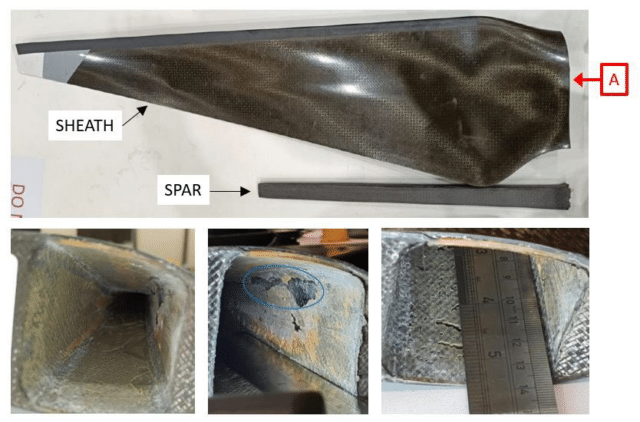
Once the adhesive bond failed to hold the blade sheath to the spar, the bending load on the blade spar fractured.
Investigators were happy that the aircraft continued flying after the EPU had been shut down and that this had not caused the blade to detach. They focused on what happened after the blade separated. The propeller, spinning at 1,200 rpm, caused pylon 3 to twist up while the propeller kept rotating. When the pylon broke, it damaged the wiring harness. The EPU3 motor wiring pulled out of the connectors. The video footage showed a bright spark of electrical arcing between the high voltage power cables and the connector body. This led to EPU4 losing its tilting function; as a result the flight computer spooled it down, as designed for a tilt fault. The rear propeller directly behind EPU3, EPU7, also shut down, likely caused by an inverter resetting.
As a result, there was no longer enough vertical thrust, although, to be fair, the prototype remained level as it descended towards the ground. A vertical descent rate of 19.5 feet per second is twice the maximum descent speed and it collapsed under the impact.
The adhesive bond seemed to have failed as a result of progressive degradation. Vertical Aerospace found two similar propeller blades, meant to be used as spares, and inspected them using CT scanning (computed tomography, basically a series of x-rays). Both blades also showed large unbonded areas as well as variations in the shape of the blade spar. They concluded that the blade structural design and the quality assurance processes had been a contributing factor to the blade detaching.
The AAIB concludes:
The blade released from EPU3 was caused by a failure of the adhesive bond between the propeller blade sheath and spar. It is likely that defects introduced in the bond when the blade was manufactured grew progressively larger during the blade’s operational service to the point that the remaining bond area was insufficient to retain the blade under normal operating loads.
Large out-of-balance loads generated by the blade release caused structural failure of the right inboard pylon, resulting in damage to the aircraft’s wiring harnesses. This caused a loss of thrust from motors 4 and 7. Whilst the aircraft’s flight control system was able to maintain a level attitude, the high rate of descent caused by the loss of vertical thrust resulted in substantial damage to the aircraft when it struck the ground.
All of the remaining blades, referred to by Vertical Aerospace as “Generation 1” have been withdrawn from use. Vertical Aerospace was already in the process of introducing Generation 2 blades which do not suffer from the same risk of bonding failure. In total, they identified 36 product and process improvements as a result of the accident. Vertical confirmed yesterday that the Generation 1 blade would not be used for any further prototypes and that they are no longer using the same supplier.
The CEO said that this would not impact their goal of having the VX4 certified by 2026 and that he believed investors would continue their support of the aircraft.

I’m not following parts of this explanation:
* Why shut down the right inboard engine after losing the left outboard engine? I’d have thought that the right outboard engine should be shut down to avoid asymmetric lift/thrust. Is this an artifact of all the propellers rotating in the same direction? (On multi-engine airplanes some do and some don’t.)
* If engine 3 was shut down, why did it lose a propeller blade? I’d have thought that a propeller that wasn’t spinning would be under less stress than one that still was.
As I read https://assets.publishing.service.gov.uk/media/6632544902f02aa4f31e4143/VA-1X_G-EVTL_06-24.pdf (the actual report, rather than front matter), EPU3 wasn’t shut down until after it lost a blade (see top of p.2); this makes sense, as the bottom of p.1 says “The aim of the test was to look at one engine inoperative performance during out of ground effect hover” (i.e., not with a matched pair of engines out).
I’m not sure I’d be willing to fly in an aircraft which had so little contact (judging by the third photo) between the spar and the surface of the propeller. Is this common in modern propellers, or just a weight-reduction hack for this aircraft? It’s nice the manufacturer thinks they’ve fixed their problems, but ISTM that a wise user would ?X-ray?sonogram?…? every blade every few hours until they’ve accumulated a lot more use time than their rated life.
You know, while I was putting this together, I thought “I really should be noting sources better or this is going to bite me on the ass” but I was in a rush and really it was all backed up by the report and it’d be fine. I’ve now been through my document history and I cannot for the world of me find the reference that I remember, which quoted the CEO saying something to the effect of performing like they expected it to in the engine out and then explained about the balancing. I thought “yes, but why the inboard engine” but it seemed quite clear.I now can’t find the text or any reference to the VX4 rebalancing in response to losing an engine. In retrospect, I picked up someone else’s error and then expanded it until it made sense. :/ I’m fixing my text above now.
Thanks for calling that out!
” it’s called the VX4. In any event, G-EVTL is the fullscale prototype of an electric high-wing aircraft with twelve propellers”
It’s got eight propellers, no?
Not any more…
OK, Harrow’s comment made me laugh out loud.
Clearly I was seeing double.
That design should remain in the pilotless category. Also crewless and, as far as I am concerned, passengerless.
A very ambitious project. Apart from the obvious need to correct design- and production flaws that appear to be at the heart of the failed test flight, I am not so certain that it won’t be necessary to amend the legislation before this sort of aircraft can fulfil its intended role.
Even if fully certified for civilian use: There are jurisdictions that require, for a commercial helicopter to be allowed to operate with passengers in an urban area, to demonstrate not only an ability to be able to do so without compromising safety, but also to have a trained fire crew with certified firefighting equipment to be present during every take-off and landing.
What kind of licence will pilots be required to carry? Fixed wing or rotary wing? Or a hybrid licence?
This contraption is too big for operating in the majority of urban areas.
Will it be necessary to demonstrate an autorotation landing, or a landing from a glide in case of emergency? Or a combination of both?
Most important: Operations as suggested, an air taxi operation, will be of little or no advantage if limited to airports. Private landing strips will also need an operating licence of some sort for commercial use.
Just landing “anywhere” that offers enough space will not be possible, not legally, for a long time, and will need again additional legislation.
A range of 100 miles may seem to be possible, more so with relatively light batteries that are being developed. But there must be a certain amount of charging points, scattered all around the proposed area of operations.
Will this aerial vehicle be allowed to operate under IMC?
And even if IFR approved, it the weather conditions mandate a flight to be conducted under IFR, this will limit the actual range to airports with the minimum of navigation equipment needed, as well as carrying the minimum battery capacity to be able to hold and fly to an alternate.
This will limit the range to, perhaps 15 miles.
The weather in the UK is not exactly generous with VMC conditions.
An interesting idea, but very far from ready to operate with pilot and passengers, even farther if it is to be a commercial operation and practically useless as an air taxi.
It may suit a billionaire to take him or her from the ancestral mansion to the local airport to transfer them to their private Gulfstream.
But even then, the beneficial impact on the environment will be negated if this air taxi is used to transfer Mr or Mrs Big to the jet.
No, a nice idea that may well, eventually lead to a practical mode of transport. Which in my opinion means that this proposal in its current form will probably never be commercially viable. On the other hand, it could provide the designers with data and experience that, in the future, may form the basis for a viable, electrically powered VTOL light aircraft.
But this is far in the future.
And will require a sizable amount of investment.
It may only be the light at the end of the tunnel.
And remember Murphy’s law:: ” the light at the end of the tunnel is the headlight of an oncoming train !”
In a one EPU inoperative scenario, there are different possible solutions to the optimisation problem of how to command the remaining units.
In general, keeping all of the remaining units running and as close to balanced as possible will minimise overall power consumption (think about effective disc area).
However, if the objective is to minimise thermal stress (and thus maximise thermal endurance) on the remaining units, it can be beneficial to command one of the units which rotates in the opposite direction to the failed unit to almost zero speed.
In the ‘minimum total power’ scenario, there will be one fewer EPU rotating in the direction of the unit which failed. Ignoring use of tilt angle to increase yaw moment, this means that the ((n/2)-1) units rotating in the same direction as the unit which failed must produce an equal net torque about the yaw axis of the vehicle to the greater number (n/2) spinning in the opposite direction, hence the greater worst-case loading.
If losses in the motors are dominated by ohmic conduction losses (‘copper losses’ as opposed to ‘iron losses’), then losses in the motor are roughly proportional to torque squared. A small increase in load causes a much larger increase in losses, which has consequences for thermal endurance in overload conditions.
A contributing element to the crash (and evidence of the very prototype nature of the aircraft) was their poor choice in control bus architecture. When the motor pylon fractured, it effectively destroyed much of the control bus.
The VX4 design used electric motors meant for cars and heavy vehicles, which meant the motors natively used the CAN bus widely used in automotive applications. CAN is great for building realtime systems with a minimum of cabling (a given CAN bus is just a single twisted pair), but it requires great care to build a robust and redundant CAN system. Since CAN is a shared-medium bus, it’s like the electrical equivalent of a hydraulic system – a break anywhere in the bus will lead to failure/misbehavior of the entire bus. Robustness requires multiple CAN busses, and just like the lessons learned from the DC-10 hydraulic system, multiple CAN busses won’t save you if they run through the same vulnerable location (like a motor pylon).
The report notes that the manufacturer is improving the CAN architecture (hopefully adopting a star topology, rather than shared busses), but the real answer adopted elsewhere in new aircraft designs has been to replace shared-medium busses (usually ARINC 429 or similar) with star switched point-to-point networks derived from Ethernet (AFDX, aka ARINC 664). CAN is really easy to work with, and very cheap – you get to pay “auto” prices for components, not “aviation” prices, but picking it for this application is emblematic of the immaturity of a lot of the e-VTOL industry.